Product categories


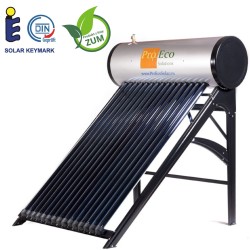
Solar Set PROECO JNCY-150
PROECO JNCY-150#B
EAN-13: 5902734700964
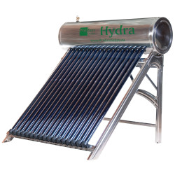
Solar set PROECO JNCY-150:
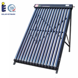
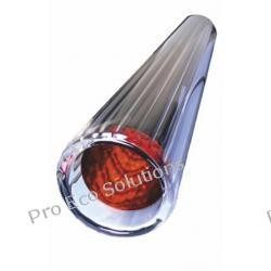
- Vacuum solar collector PROECO JNSC 15-58/1800
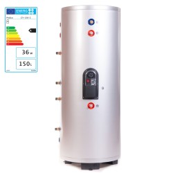
- Water tank 150 l. - stainless steel with two copper coils
- Solar station 12l. with controller SR868C8
6.666,67 tax excl.
The lowest price of this product in last 30 days was 8,200.00 PLN.
This pack contains

")
Solar set PROECO JNCY-150:
- Vacuum solar collector PROECO JNSC 15-58/1800
- Water tank 150 l. - stainless steel with two copper coils
- Circulation pump Wilo Star-RS15 / 6
- Expansion vessel 12l.
- SR868C8 controller with 3 temperature sensors
- Solar fluid to fill the system - MPG ECO-SOL 32 - 10kg
Use:
An ideal solution for obtaining utility hot water and as a central heating system support for single-family houses, guest houses, recreation centers, pools, hospitals, production facilities etc.
Design:
The solar collector consists of vacuum tubes made of borosilicate glass. High operational safety of borosilicate glass has been achieved thanks to the use of an appropriate mix of SiO2 and B2O3 oxides, which results that the product has high chemical resistance as well as extraordinary purity and uniformity. Borosilicate glass is environment-friendly and can be recycled many times. The process of thermal annealing (hardening) was also used. Together with the low thermal expansion typical for borosilicate glass gives it a particularly high resistance to changes of temperature in comparison to standard glass. Tubes are resistant to hail size up to 25 mm. The use of tubes with a diameter of 47 mm and 58 mm allows concentric placement of one inside the other. The air between the pipes is pumped out, and the pipes are welded together. The vacuum between the pipes is an excellent insulator and prevents the loss of heat. In the process of triple magnetron metallization, an absorber (compound absorbing sun rays and transforming them into heat energy) is applied. The new special absorption layer ALN/AIN-SS/CU with the addition of copper is the next generation of absorption layers. The next layer, that is, the AL/N/AL layer, is characterized by higher efficiency (up to 12%) and excellent absorption properties of direct and diffused radiation. Additional layers of the absorber are designed to keep as much energy as possible inside the tubes and prevent heat loss through infrared radiation. The inside of the vacuum tube can heat up to 300ºC. Inside the vacuum tubes the so-called "heat pipes" are mounted. Aluminum radiators inside the vacuum tubes support the process of transfer of energy to the copper heat pipes. The lowering of pressure in the pipe by sucking the air out, is done according to the principle of lowering the boiling point along with the pressure drop. The liquid/fluid inside the heat pipe exchanger boils already at 25ºC. Copper used in the production of the heat pipe is free of oxygen, which ensures the possibility of long and reliable operation.
High efficiency of the collector results from the ability to absorb diffused radiation (for example, on cloudy days) and maximum reduction of heat loss. Energy is obtained not only from direct sunlight but also from reflected light. The collecting manifold of the collector is made of copper pipe. Inside it, copper sleeves were mounted, in which a heat pipe condenser is inserted. To achieve better contact between the copper surfaces and thus more efficient heat transfer, high-temperature heat conductive pastes are used. The collecting main is thermally insulated with mineral wool. Despite the fact that it has slightly worse insulation properties than polyurethane foam, it is a better solution in this case. Mineral wool does not oxidize and is more resistant to high temperatures that can occur, for example, when the fluid circulation in the installation stops. The collecting main also has room for the temperature sensor. The housing of the collecting main and its frame are made of aluminum. The use of lightweight metals is quite important when installing collectors on building roofs.
The tank (hot water tank) is made of SUS 304 stainless steel with a thickness of 1.4 - 2.0 mm and is insulated with polyurethane foam with a thickness of at least 50 mm. In this case, the foam was used because it has better insulation properties, and the maximum temperature does not exceed 100ºC. The tank is equipped with two copper coils. Thanks to this, they can work with a second heat source, for example, a boiler. A temperature sensor is also installed inside the tank.
Data from temperature sensors are downloaded by an electronic control system. It enables automatic activation of the circulating pump forcing the circulation of fluid in the system. An expansion vessel is used to compensate for the increase in fluid pressure in the system due to the increase of temperature.
Principle of operation:
Energy from the sun rays heats the inside of the vacuum tubes. The heat from the inside of the pipe is transferred to the "heat pipes" through the aluminum radiators. After a while, at 25 ºC the liquid in the "heat pipe" begins to evaporate. The vapor goes up to the exchanger head (condenser) where it releases heat through the collecting main and condenses. It flows down again into the "heat tube" to repeat the whole process. The heating medium flowing through the collector (for example, glycol) has no contact with the vacuum tubes and the absorber applied on them, but only receives heat from the "heat tube" condenser. The connection of the "heat pipes" with the heat exchanger (in which the glycol flows) is "dry".
The simplest and cheapest system is a gravitational system. The heating medium heated in the collector goes to the top of the tank without the use of a circulating pump, then after releasing the heat in the tank, the cooled medium returns to the collector. In such system, it is necessary to place the tank above the collectors. In practice, this forces the collectors to be placed on frames on the ground and the storage tank on the first floor in the building.
The second solution used is a system with forced circulation. It has no disadvantages of gravitational circulation installations, but it is necessary to use a pump and an automatic control system. Usually, tanks equipped with two coils (bivalent tanks) are used in such circulation. Thanks to them work with two heat sources is possible. The solar system is connected to the lower coil and heating boiler to the upper coil. With favorable conditions (the temperature of the medium in the collector is 5 to 8 degrees Celsius higher than the temperature of the water in the tank), the circulating pump is activated, which pumps the heated medium from the collector to the coil in the tank.
In the event of a vacuum tube failure, the entire system will continue to operate, although the efficiency of the system will be lower. There are no fluids in the vacuum tubes, which means that the tube can be dismantled at any time without draining the system.
Installation method:
Vacuum collectors, thanks to the possibility of working all year round (have higher average annual efficiency) can work not only for hot water but also can also be used to preheat the heating medium for central heating. A suitable solar system can also be used to produce process heat or to dry agricultural produce. A well designed and created system allows for obtaining heat that can provide coverage of up to 40% of the total annual heat demand of a single-family house and up to 75% of the energy needed to heat utility water.
When installing collectors on buildings, various mounting systems are used. On roofs with a slope of approximately 45º, the collectors are mounted directly to the structure of the roof. This is the most common mounting method in Europe. Sometimes there is a situation in which the roof slope does not have the right angle of inclination. A spatial frame correcting this angle is then made. On a flat roof, terrace, or on the ground, it is necessary to use a supporting structure. Vacuum collectors can also be mounted on vertical surfaces such as facades, balcony railings, and balustrades. Make sure that collectors mounted in this way harmonize with the architectural concept of the building. The frame can also be made in the form of a roof above the entrance door or stairs to the terrace. When installing the collectors on the ground next to the building, in addition to sunlight, you should also pay attention if the collectors are not an unnecessary obstacle. The distance between the collectors and the heat receiver may also be significant to minimize energy losses.
In addition to obtaining more energy in comparison to flat collectors and easier installation, repairs and maintenance (thanks to the possibility of replacing individual tubes in the event of damage) are also easier. Damage to flat collectors is very often associated with the replacement of the entire collector surface. When choosing the mounting location for collectors, you do not have to worry about easy access to them for the future. Flat or vacuum collectors based on U-tubes are fully assembled at the factory or just before they are placed on the roof. Then they are carefully transported to the roof. Due to the large dimensions, weight, and fragility, it is sometimes very difficult. Our collectors are much easier to install. Individual elements are transported to the roof individually. First, the collector mounting is assembled, then its aluminum frame and the upper part (collecting main). Due to the lack of elements made of glass at this stage of assembly, there is no problem with conveniently connecting the collector to the system. When the collector frame is already installed, you can proceed to install the vacuum tubes.
Systems offered by us can be freely configured. Sometimes it is useful to install a large tank, which is used as a heat buffer and hot water storage (for example, on cloudy and rainy days when the energy obtained from the collectors is slightly lower). Sometimes it is better to install collectors with a larger surface area. We are sure then that even when the sun's rays are low, the higher power of the collectors will heat the water quickly. It is convenient in winter but causes problems in summer. Most systems simply overheat under strong sunlight. There is a problem with an excess of heat. In our systems, this problem can be easily eliminated. If a larger collector surface is installed, all that must be done is to remove a pair of tubes before summer to reduce the power in such way.
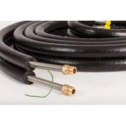
We recommend using double pipes pre-insulated with synthetic rubber foam and increased thermal resistance for quick and easy connection of the collector with the accumulation tank. The pipes are made either of stainless steel or soft copper. Thanks to their flexibility, no additional fittings and connectors are needed between the collector and the tank. They are also equipped with an integrated control cable (for the temperature sensor in the collector). In addition to maintaining the highest technical parameters to minimize energy losses, this system significantly reduces the time of installing and increases its reliability.
Advantages:
- Higher efficiency of the vacuum collector with the "heat pipe" system (work throughout the year).
- Possibility to choose different sizes of collectors for different sizes of tanks.
- Damage to the vacuum pipe from the "heat pipe" does not turn off the entire system, but only reduces the efficiency of the collector.
- Lower likelihood of clogging of the collector, which may occur with flat or U-tube collectors.
- Possibility of coupling with a central heating system to reduce energy costs.
Installation and operating instructions:
Manual PROECO JNSC.pdf
Utility hot water tanks for solar sets
|
------------------------------ |
Collector: |
|
Color of the collector frame |
black |
|
Color of the collector main |
black |
|
'Number of vacuum tubes |
15 |
|
''Heat pipe'' use |
yes |
|
Size of the vacuum tube |
diameter: 58 mm outside/ 47 mm inside, thickness of wall: 1,6 ± 0,15 mm, length: 1800 mm |
|
Type of absorber |
(aluminum nitride with copper and steel layers) CU/SS-ALN(H)/SS-ALN(L)ALN |
|
Efficiency of the absorption |
α = 0.92~0.96 (AM1.5) |
|
Lossy emission |
ε = 0.04~0.06 (80℃± 5℃) |
|
Degree of vacuum |
P. ≤5.0X10ˉ³ (PA) |
|
Temperature of stagnation |
260~300℃ (inside empty tube) |
|
Average heat loss |
ULT 0.4~0.6 W/(m2~﹡℃) |
|
Resistance to hail |
Φ25 mm |
|
Lifespan |
>15 years |
|
Resistance to wind |
180 km/h |
|
Capacity |
100 l. |
150 l. |
200 l. |
250 l. |
300 l. |
500 l. |
|
Internal diameter of tank |
370 mm |
370 mm |
470 mm |
470 mm |
470 mm |
600 mm |
|
External diameter |
470 mm |
470 mm |
560 mm |
560 mm |
560 mm |
700 mm |
|
Material of the inside of the tank |
Stainless steel SUS304 1.2 mm |
Stainless steel SUS304 1.2 mm |
Stainless steel SUS304 1.5 mm |
Stainless steel SUS304 1.5 mm |
Stainless steel SUS304 1.5 mm |
Stainless steel SUS304 2 mm |
|
Material of the outside of the tank |
Galvanized steel 0.55 mm |
Galvanized steel 0.55 mm |
Galvanized steel 0.55 mm |
Galvanized steel 0.55 mm |
Galvanized steel 0.55 mm |
Galvanized steel 0.6 mm |
|
Type of thermal insulation |
Polyurethane foam |
Polyurethane foam |
Polyurethane foam |
Polyurethane foam |
Polyurethane foam |
Polyurethane foam |
|
Thickness of insulation |
50 mm |
50 mm |
45 mm |
45 mm |
45 mm |
50 mm |
|
Number of exchangers (coil) |
2 |
2 |
2 |
2 |
2 |
2 |
|
Length of coil |
15 m (copper) |
15 m (copper) |
15 m (copper) |
15 m (copper) |
15 m (copper) |
15 m (copper) |
|
Diameter/thickness of coil |
12 mm / 1.0 mm |
12 mm / 1.0 mm |
12 mm / 1.0 mm |
12 mm / 1.0 mm |
12 mm / 1.0 mm |
12 mm / 1.0 mm |
|
Exchanger connector |
1/2’’ |
1/2’’ |
1/2’’ |
1/2’’ |
1/2’’ |
1/2’’ |
|
Tank connector |
3/4’’ |
3/4’’ |
3/4’’ |
3/4’’ |
3/4’’ |
3/4’’ |
|
Height of the tank |
1040 mm |
1440 mm |
1250 mm |
1520 mm |
1810 mm |
1850 mm |
|
Size of packaging |
550 x 550 x 1120 mm |
550 x 550 x 1500 mm |
645 x 645 x 1330 mm |
645 x 645 x 1580 mm |
645 x 645 x 1870 mm |
780 x 780 x 1950 mm |

- Heater capacity (l.):
- 144
- Average demand for:
- for 2 to 4 person
- Hot water collection:
- under pressure from the water mains
- Surface mounting:
- for flat or sloping to 80 degrees
- Number of vacuum tubes (pcs):
- 15
- Vacuum tube size (mm):
- 58 mm / 1800 mm
- Use of Heat-Pipe:
- YES
- Water tank:
- stainless steel SUS 304 0,4 mm
- Heat exchanger in the tank:
- copper coil
- Cover of the tank:
- stainless steel SUS 304
- Bracket:
- galvanized steel, powder coated
Customers who bought this product also bought:
The lowest price of this product in last 30 days was 2,249.00 PLN.
The lowest price of this product in last 30 days was 2,699.00 PLN.
The lowest price of this product in last 30 days was 48.00 PLN.